Saturday, October 15, 2011

Basic Electrical and Electronic Circuits

Basic Electric Circuit
The first thing a beginner needs to know to understand a system of electrical circuits and electronic circuits is the understanding of basic electrical theory including electron and basic unit of electrical measurement such as the value of current, the value of voltage, and the value electrical power; the introduction of codes and electric and electronic symbols; understanding of basic electric and electronic formulas; understanding of basic electrical circuits and electronics; and ways of working components.

In principle, the basic electrical circuit consists of three parts:
  1. Voltage source: Voltage source (Power Supply) can be either voltage AC (Alternate Current) 220-240 VAC from the power company or a DC voltage (Direct Current) like an Accumulator (Battery Cell)
  2. Conductor: Conductor can be a cooper wire, cable, or other objects that are conductive.
  3. Load:  Load can be either electric or electronic devices such as televisions, refrigerators, washing machines, computers, electric motors, radios, lamps, LEDs, etc.
The third part of the electrical circuit can be connected or disconnected by a switch. When the switch is closed, electric current will flow from the source voltage through the load so that the load will work, and will be disconnected when the switch is open (disconnect) to turn off the load.

Basic Electronic Circuit

If the resistance of the conductor ignored or considered to be zero (0 Ohm). The greater voltage source, the greater current flowing to the load. The larger the load resistance, the smaller current flowing in the electrical circuit. In this condition shall apply Ohm's Law.

Ohm's law is a statement that the electrical current flowing through a conductor is always proportional to the applied potential difference to it. A conductive object will be in accordance with Ohm's law if the resistance value does not depend on the value and polarity of the potential difference. Although this statement does not necessarily apply to all types of conductors, but the term "law" still used by historical reasons.

Mathematically Ohm's law written by the equation:

Ohm Law

"I" is electric current flowing in a conductor in Amperes (A), "V" is the voltage present at both ends of the conductor in Volts (V), and "R" is the resistance contained in a conductor in Ohm . This law was initiated by George Simon Ohm, a physicist from Germany in 1825 and published in a paper titled The Galvanic Circuit Investigated Mathematically in 1827. (Wikipedia)
Resistance, Voltage, and Current

Voltage and Current
The meaning of Resistance, Voltage, and Current
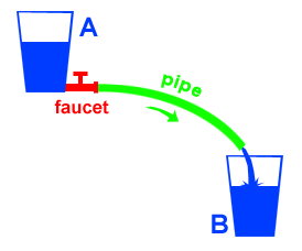
To understand the voltage and ampere we can see the example of two glasses are placed in different positions (left image). Glass "A" at the top position and glass "B" in the lower position. Glass "A" and glass "B" is connected with the pipe and in glass "A" attached faucet and filled with some water.

If the faucet is opened, the water will flows from glass "A" to the glass "B" through the pipe. The amount of water current that flows depends on the difference in height between the two glasses and depends on the size of the facet opening. The greater the difference in height between the two glasses, the greater the flow of water flowing through the pipe.

This height difference is assumed as the voltage where glass "A" is the positive pole and glass "B" is the negative pole. Pipe is assumed to be the connecting cables (connectors) and faucet as a switch. If the faucet is closed, the water will not flow through the pipe but if the faucet is opened, the water will flow from glass "A" to the glass "B" through the pipe.

The above example applies also to the electric current, if the switch is disconnected, the electric current will not flow but if the switch is connected, the electric current will flow from the positive pole toward the negative pole through the cable (the connector).

Unit voltage is Volt (V) and the unit of electrical current is Amperes (A). The value of the current that flows influenced by the value of the resistance in an electrical system or a in electronic circuits. Resistance can be assumed by the size of the pipe or the size of the opening faucet. Resistance unit is Ohm.

Voltage is the cause and current is the effect 
Voltage is the source to make the current flows and current will flow if the circuit is complete, meaning there are voltage source, connector, and the load. 


Current and Voltage

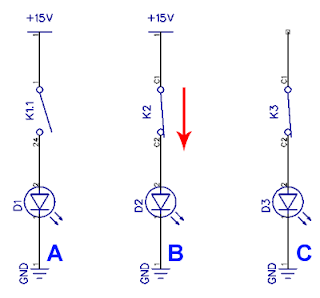
Note the electronic circuits above. In the picture "A", there are a voltage source, connector, and the load but no current flows because the switch is open; In picture "B" there are a voltage source, connector, and the load and the conditions of switch  is closed so the current will flow from the positive pole to negative pole through connector; In picture "C" there will be no current flowing though there are connector, the switch is closed, and the load, but there is no voltage source.

Friday, October 14, 2011

Electric and Electronic Symbols

Electric Symbols
Before studying the electrical and electronic, the things we should know are electrical and electronic symbols to learn more easily, especially when reading circuits and electrical schematics and electronics in a system.

By using these symbols, schematics will be easily constructed and easily understood so that the assembly process would be much easier. Below are some symbols of electrical components and electronic components.

Usually a professional electrician will read electrical schematics before the installation process. Besides the application of electrical symbols and electronic symbols can help finding an error or fault during the repair time.

SYMBOL COMPONENT NOTE
Connections
Simbol Kabel Cable Connection Connected wire (conductor)
Connected Symbol Connected Cable Connected
Connected Symbol Disconnected Cable Disconnected
Switch and Relays
Switch Symbol Toggle Switch SPST Disconnect when open
Switch Symbol Toggle Switch SPDT One on - one off
Switch Symbol Switch Push-Button (NO) Connect when the button is pushed
Switch Symbol Switch Push-Button (NC) Disconnect when the button is pushed
Switch Symbol DIP Switch Multiswitch
Switch Symbol Relay SPST Connection (Open and Close) by electromagnetic 
Switch Symbol Relay SPDT
Switch Symbol Jumper Connected by jumper
Switch Symbol Solder Bridge Connected by soldered
Ground (GND)
Ground Symbol Earth Ground Zero reference
Ground Symbol Chassis Ground Body (Chassis) Ground
Ground Symbol Common/ Digital Ground
Resistor Symbols
Resistor Symbol Resistor Resistor
Resistor Symbol Resistor
Variable Resistor Potensio Meter Variable Resistor
Variable Resistor Potensio Meter
Variable Resistor Variable Resistor Variable Resistor
Variable Resistor Variable Resistor
Condensator Symbols
Condensator Symbol Bipolar Condensator Condensator
Condensator Symbol Nonpolar Condensator
Condensator Symbol Bipolar Condensator Electrolytic Condensator (ELCO)
Condensator Symbol Bipolar Capacitor Electrolytic Condensator (ELCO)
Condensator Symbol Kapasitor Variable Condensator yang nilai kapasitansinya dapat diatur
Inductor Symbols
Induktor Symbol Inductor, spul, coil Generate electromagnetic
Induktor Symbol Induktor dengan inti besi Generate electromagnetic
Induktor Symbol Variable Inductor Variable Inductor
Power Supply
Power Symbol DC Source Generate DC Voltage Source
Power Symbol Current Source Menghasilkan sumber arus tetap
Power Symbol AC Source Generate AC Voltage Source
Power Symbol Generator Generate Electric Voltage
Battery Symbol Battery Generate DC Voltage
Battery Symbol Multicell Battery Generate DC Voltage
Regulator Variavle Source Voltage Voltage Source
Regulator Variable Current Source Current Source
Meter Symbols
Volt Meter Volt Meter Measure voltage 
Ampere Meter Ampere Meter Measure Current
Ohm Meter Ohm Meter Measure Resistance
Watt Meter Watt Metter Measure Electrical Power
Lamp Symbols
Lamp Symbol Lamp Produce light when electrified
Lamp Symbol Lamp
Lamp Symbol Lamp
Diode Symbols
Diode Symbol Diode Serves as a rectifier of electrical current that can flow in one direction (forward biased)
Diode Zener Zener Diode DC Voltage stabilizer
Diode Schottky Schottky Diode Diode with low drop voltage, typically found in logic ICs
Diode Varactor Varactor Diode Varactor
Diode Tunnel Tunnel Diode Tunnel Diode
LED LED (Light Emitting Diode) Produce light when electrified DC in one direction
Photo Diode Photo Diode Generate electric current when it gets light
Transistor Symbol
Transistor NPN Bipolar NPN Transitor The electrical current will flow (EC) when the base (B) given a positive
Transistor PNP Bipolar PNP Transistor The electrical current will flow (CE) when the base (B) were given negative
Transistor Darlington Darlington Transitor The combination of the two bipolar transistors to increase the reinforcement
Transistor JFET N JFET-N Transistor Field Effect Transistor N channel
Transistor JFET P JFET-P Transistor P channel Field Effect Transistor
Transistor NMOS NMOS Transistor N channel MOSFET transistor
Transistor PMOS PMOS Transistor P channel MOSFET transistor
Other Symbols
Electric Motor Motor Electric Motor
Transformer Transformer, Transformator Step-Up and Step-Down Voltage
Electric Bell Electric Bell Sounds when electrified
Buzzer Buzzer Producing sound as electrified buzz
Fuse Safety. Will disconnect when the current exceeds the capacity
Fuse Fuse
Bus Symbol Bus Consists of many lines of data or address lines
Bus Bus
Bus Bus
Opto Coupler Opto Coupler As with insulation between two different settings. Connected by light
Loud Speaker Speaker Transform electrical signals into sounds
Mic Mic, Microphone Change the voice signal into an electric current
Op-Amp Op-Amp, Operational Amplifier Amplifier input signal
Schmitt Trigger Schmitt Trigger Reduce noise
ADC ADC, Analog to Digital Change the analog signal into digital data
DAC DAC, Digital to Analog Converts the digital data into analog signals
Oscillator Crystal, Ocsilator Producing pulses
Antenna Symbols
Antenna Antenna Radio signal transmitters and receivers
Antenna Antenna
Antenna Dipole Antenna The combination of simple Antenna
Logic Symbols
NOT Gate NOT Gate The output will be the inverse input
AND Gate AND Gate Output will be 0 if one of input 0
NAND Gate NAND Gate The output will be 1 if one input 0
OR Gate OR Gate The output will be 1 if one input 1
NOR Gate NOR Gate Output will be 0 if one input 1
EX-OR Gate EX-OR Gate Output will be 0 if the input is equal
D-Flip-Flop D-Flip-Flop Can serve as data storage (memory)
Simbol Multiplexer Multiplexer 2 to 1 Selecting one of the input data to be sent to the output
Multiplexer Multiplexer 4 to 1
D-Multiplexer D-Multiplexer 1 to 4 Selecting the input data to be sent to one output